Is It Possible That the machines building fiber optic cable production machinery serve as the unseen force that at last provides true gigabit access to every American home? This article examines the recent breakthroughs in FTTH Cable Production Line Technology. These advancements are revolutionizing broadband network infrastructure and accelerating fiber to the home technology across the United States.
FTTH Cable Production Line

Fiber Draw Tower

Fiber Coloring Machine
Modern advancements in automation, precision engineering, and AI-driven inspection are substantially lowering production costs and boosting quality. This synergy makes high-speed internet technology more trustworthy and simpler to implement for service providers and municipalities.
Global optical cable output now exceeds hundreds of millions of kilometers annually. This surge is driven by 5G deployments, hyperscale data centers, and the growing demand for streaming and remote work. The subsequent sections will examine automation and Industry 4.0, the use of low-loss materials, AI quality control, innovative cable designs such as bend-insensitive fiber and flat drop microcables, and the pursuit of sustainability in production lines.
Telecommunications manufacturing, network planning, and procurement professionals will gain valuable insights. These insights are on selecting the right fiber optic cable production machinery and optimizing processes. They are designed to meet regional deployment needs and future bandwidth growth.
FTTH Cable Production Line Technology
The term encompasses the machinery, control systems, and materials transforming optical preforms into deployable fiber cables. It encompasses fiber drawing and coating, SZ stranding, ribbon formation, extrusion of jackets, armoring, taping, automated testing, and final take-up systems. Each step’s precise control defines the fiber optic cable production process, ensuring consistent performance.
The manufacturing chain demands stringent tolerances. SZ stranding systems align dozens of strands with micron-level tension precision. Extrusion lines employ servo-driven extruders and laser micrometers to maintain jacket thickness within ±0.02 mm. Such precision minimizes variability, cutting attenuation and streamlining field splicing.
Standards and regulatory frameworks significantly influence manufacturing decisions. Compliance with ITU-T recommendations, such as G.657, and regional fire codes like CPR in Europe, is essential. Meeting these standards ensures products align with the broader broadband network infrastructure.
Quality in production directly impacts network economics and service delivery. Lower attenuation and consistent geometry reduce splice loss and extend reach. This enhances reliability for carriers, ISPs, and utilities, while lowering the total cost of ownership for FTTH deployments. The growing demand for symmetrical multi-gigabit services, 5G backhaul, and data center interconnect is driving the scale-up of modern lines.
Comparing key process components and tolerances reveals their impact on output and quality.
| Process Component | Standard Control | Effect on Performance |
|---|---|---|
| Fiber drawing and coating | ±1°C temperature control; coating concentricity ±5 µm | Stable fiber profile; lower bending-related loss |
| SZ stranding and ribbon formation | Micron-level tension regulation; synchronization at 0.5 ms | Even fiber pitch; more predictable connector and splice results |
| Extrusion & jacket thickness | Laser micrometer feedback; ±0.02 mm tolerance | Reliable mechanical protection; consistent installation response |
| Tape wrapping and armoring | Servo-controlled feed rate; layer alignment control | Enhanced crush protection; supports compliant aerial and buried specs |
| Automated testing and take-up | OTDR and insertion-loss verification at production speed; controlled winding tension | 100% traceable quality; reduced rework and field failures |
Manufacturers like Corning, Prysmian Group, and Sumitomo Electric focus on tighter process control to meet operator expectations. Continuous advancements in the fiber optic cable production process enable networks to scale while maintaining performance in the last mile of broadband network infrastructure.
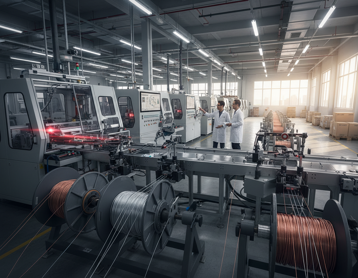
Automation And Industry 4.0 In Fiber Optic Cable Production
Factory floors for fiber optic cable production machinery now mirror advanced manufacturing plants from other industries. Smart controls, synchronized stages, and data-driven decision making raise output and protect quality. These shifts shorten commissioning time for new product families. They let telecommunications equipment manufacturers pivot between armored aerial lines and microcable runs with minimal downtime.
Smart machinery and PLC integration
Programmable logic controllers coordinate stranding frames, ribbon formers, and take-up units to keep tension within sub-0.01mm windows. Servo-driven extrusion coupled with laser micrometers enforce ±0.02mm jacket thickness. The result is fewer rejects, less rework, and consistent optical performance on every reel.
Edge computing and process orchestration
Local edge servers ingest terabytes of telemetry each day. They drive low-latency closed-loop adjustments and push immediate alerts when deviations occur. This approach keeps optical fiber cable equipment running at peak efficiency. It supports real-time quality assurance during long production runs.
AGVs, material handling, and workflow gains
Automated Guided Vehicles move heavy cable drums with millimeter-level repeatability. Laser-navigated AGVs reduce manual handling injuries and speed material flow between extrusion, curing, and drum stations. This automation lowers labor costs while raising throughput on ftth cable production line technology setups.
Benefits for manufacturers and the supply chain
- Increased throughput with consistent results
- Accelerated prototyping and reduced time to market
- Lower labor exposure and reduced operating cost
- Stronger connectivity between optical fiber cable equipment and enterprise platforms
Industry ecosystem and adoption
Leading telecommunications equipment manufacturers pair PLCs with robotic arms, AGVs, and industrial IoT stacks to reach Industry 4.0 goals. This integration creates a resilient production base. It is able to adapt as demand shifts toward denser, more complex FTTH offerings.
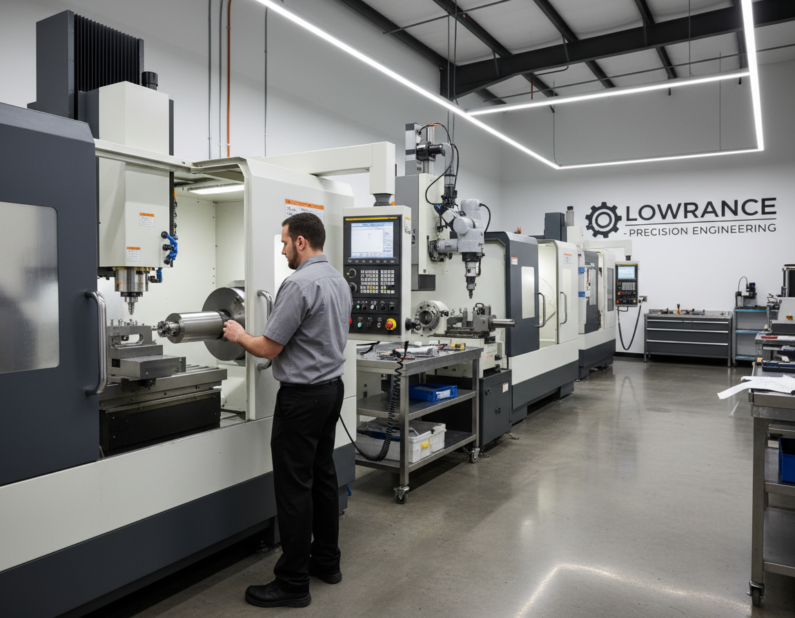
Precision Engineering Breakthroughs For Lower Attenuation
Advances in materials and mechanical design are driving down loss in modern fiber lines. Engineers pair ultra-low loss fiber with tighter coating control to reduce intrinsic and bending attenuation. These gains matter to network operators who want longer spans and fewer amplifiers in high-speed internet technology deployments.
The fiber optic cable production process now favors smaller coated diameters such as 180µm and 160µm. These sizes let manufacturers increase fiber count and build denser microcables without sacrificing handling or optical stability.
Low-Loss Glass And Advanced Coatings
Manufacturers use improved glass formulations that lower Rayleigh scattering and reduce baseline attenuation. Ultra-low loss fiber variants extend reach for long-haul and high-capacity links while easing repeaters and amplifier requirements.
Coating chemistry has progressed too. UV-cured acrylate systems cut microbending loss by roughly 40% compared with earlier generations. That performance drop helps maintain signal integrity in cramped ducts and tight bends common in FTTH and 5G backhaul networks.
Central Strength Members And Mechanical Design
Mechanical design updates center on robustness and dimensional control. Fiber-reinforced plastic (FRP) rods with tensile strengths near 1.2 GPa serve as central strength members. They limit elongation during pulling and boost crush and bending resilience.
Water-blocking advances use swellable yarns and grease-free gel compounds to achieve near-complete moisture resistance. These measures protect optical paths and raise in-service reliability for cable installations in challenging environments.
These precision engineering steps integrate directly into fiber optic cable manufacturing workflows. When the production line aligns glass, coating, and mechanical specs, attenuation falls and networks gain reliability. That alignment shortens time to service for operators deploying modern broadband and high-speed internet technology.
Quality Control 4.0 And AI-Powered Inspection
Smart factories for fiber optic cable production now embed inspection systems that run continuously. These systems combine machine vision, machine learning, and automated testers to watch every reel and spool. The result is tighter feedback during the fiber optic cable production process and fewer surprises in the field.
AI models score coating uniformity, microbends, and surface defects at line speed. They cross-reference process telemetry from fiber optic cable production machinery and predict deviations hours before a reel moves to final spooling. This allows for in-line adjustments without stopping the line.
Automated OTDR integration performs 100% attenuation testing on every length. Modern OTDR systems using 1550nm sources map loss across reels and flag changes as small as 0.01 dB/km. Inline OTDR logs feed edge analytics for rapid root-cause tracing when a batch shows anomalies.
Robotic bend-radius simulators apply repeated stress cycles while monitoring macrobend loss. These testers validate compliance with ITU-T G.657 and customer bend specifications by running controlled bends at multiples of the cable diameter. Test outcomes are tied to batch IDs for traceability.
Thermal cycling chambers stress jackets and splices across wide temperature ranges. Environmental tests up to +85°C and down to -60°C confirm stability for extreme climates. Automated logs record each chamber run and link results to production lots.
Quality control 4.0 reduces returns and field failures by making 100% in-line testing routine. Edge analytics and OTDR integration shorten diagnosis times and improve regulatory compliance. Broadband operators see fewer truck rolls and better lifecycle performance for FTTH networks.
Cable Design Innovations For FTTH Deployments
New cable designs address common field challenges in fiber to the home technology. Engineers focus on durability, space economy, and speed of activation. These trends reduce installation time and lower long-term operational costs.
Bend-Insensitive Fiber Benefits For MDUs And Tight Routing
Bend-insensitive fiber maintains signal strength when routed around corners and through confined spaces. ITU-T G.657 compliant fibers minimize attenuation at tight radii, protecting links in multi-dwelling units and behind baseboards. Prysmian’s BendBright family and BendBrightXS exemplify how smaller coated diameters facilitate routing without compromising optical performance.
Flat Drop And Microcable Options For Flexible Deployments
Flat drop cable remains a preferred choice for aerial self-support, duct installs, and direct burial in North America. Its profile accommodates narrow pathways and enhances aerial spans with appropriate clamps. High-fiber-count flat drops necessitate enhanced radial strength and more robust hardware for longer spans.
Microcable technologies reduce outside plant profiles to 8 mm or less. Microcables and air-blown systems enable capacity addition inside existing ducts and congested corridors. These approaches reduce civil works, lower labor costs, and facilitate incremental network growth for urban and campus builds.
Pre-Connectorized Solutions To Speed Field Activation
Pre-connectorized solutions offer factory-terminated, plug-and-play assemblies that minimize field fusion and connector errors. Hardened outdoor connectors and vendor offerings like Prysmian’s ezDROP simplify mass rollouts and enhance first-pass yield. Service teams experience fewer truck rolls and faster service turn-up for smart city and 5G edge projects.
| Cable Design | Primary Benefit | Common Use Case | Deployment Factor |
|---|---|---|---|
| Bend-insensitive fiber | Stable performance in tight-radius routing | Multi-dwelling units, indoor routing, compact pathways | Select ITU-T G.657 variants for indoor runs |
| Flat drop cable | Versatile installation modes | Aerial service drops, direct burial, duct installs | Use proper clamps and radial-strength hardware |
| Microcable solutions | Small footprint and incremental capacity | Microduct installs, congested urban ducts | Air-blown systems require compatible blower tools |
| Factory-connectorized solutions | Faster field activation and fewer errors | Large deployments, rapid activation | Plan for standardized connector interfaces |
Sustainability And Energy Efficiency In Production Lines
Manufacturers in the fiber optic cable industry are embracing greener practices to reduce costs and meet consumer demands. Facilities prioritizing sustainable production witness improvements in operational efficiency and brand reputation. These advancements impact power systems, cooling, raw materials, and waste management.
Recovered energy systems strategies are becoming prevalent on extrusion lines and take-up reels. Regenerative braking on motor-driven spools returns power to the grid, thereby lowering net consumption. Studies indicate that energy recovery can reduce drive energy use by up to 32 percent in retrofitted reels.
Closed-loop cooling and chiller-less extrusion systems are reducing water demand. Adiabatic cooling can decrease water use by as much as 75 percent, particularly beneficial in water-scarce areas. Plants employing closed-loop cooling systems, in conjunction with heat exchangers, maintain temperature control while reducing utility expenses.
Recyclable jacket materials are transforming the disposal of cables. New polypropylene-based and modified polymer compounds meet mechanical and fire-safety standards, enabling higher recycling rates. Suppliers like Borealis and LyondellBasell are developing compounds that support the circular economy in cable jackets.
Process optimization minimizes scrap before recycling. Precision extrusion, in-line laser measurement, and real-time analytics reduce off-spec runs. Digital twins enable engineers to refine parameters, enhancing batch yields and reducing material waste.
Regulatory pressures and corporate ESG goals are compelling operators to favor vendors with transparent sustainability metrics. Municipal procurement teams and large network operators increasingly consider lifecycle impacts when selecting suppliers.
| Area | Common Improvement | Key Benefit |
|---|---|---|
| Regenerative reel drives | Up to 32% energy reduction | Lower power costs and less peak demand |
| Closed-loop cooling and adiabatic systems | Approximately 75% reduction in water use | Lower water expenses and better compliance in arid areas |
| Recyclable cable jacket materials | Higher post-consumer recycling rates | Stronger circular economy support and easier disposal |
| Inline inspection and digital twins | Double-digit cuts in scrap and off-spec runs | Improved yields with less wasted material |
| Sustainability reports and certifications | Stronger procurement positioning | Stronger appeal to network operators |
Implementing these measures enhances the resilience of fiber optic cable manufacturing. It leads to lower lifecycle costs and easier compliance. Manufacturers integrating energy recovery and recyclable jacket materials position themselves for growth in the green procurement market.
Emerging Technologies Shaping Cable Manufacturing
New technologies are transforming the design and operation of fiber optic cable production machinery. These innovations expedite commissioning, diminish prototyping cycles, and empower manufacturers to test process alterations without halting production.
Digital twins create virtual replicas of entire production lines and novel cable designs. Engineers at Corning and Prysmian leverage these models to validate footprint, material flow, and layout before physical construction. Studies indicate commissioning can be up to 60% swifter when teams execute virtual scenarios and optimize layouts beforehand.
Digital twins facilitate expedited R&D for bespoke items such as armored variants and anti-rodent jackets. Virtual testing minimizes the necessity for physical prototypes and accelerates market entry. Teams can simulate process modifications, observe material interactions, and refine equipment parameters in a risk-free milieu.
AI systems introduce predictive capabilities on the factory floor. Machine learning scrutinizes 50+ parameters to forecast failures and quality deviations hours in advance. This AI predictive maintenance lessens unplanned downtime and elevates overall equipment effectiveness for high-volume lines.
Manufacturers like Siemens and ABB integrate AI with edge computing, enabling models to operate proximal to machines. Alerts prompt targeted inspections, spare part staging, and corrective actions before a fault halts production. This strategy maintains yield and shortens mean time to repair.
Quantum fiber sensing and distributed monitoring extend capabilities beyond production to the deployed cable. Embedded Brillouin and distributed acoustic sensing provide continuous strain and temperature data across extensive spans.
Integration of quantum fiber sensing enhances network diagnostics and supports structural health monitoring. Field teams acquire actionable insights when sensing data is linked to manufacturing records and test logs. This connection enables tracing anomalies to specific production batches.
Combined workflows—digital twins plus AI predictive maintenance—accelerate both commissioning and product development. Manufacturers embracing these tools can respond more swiftly to market fluctuations and deliver higher-value, differentiated cables.
Market-Driven Production Adaptations And Regional Needs
The global demand for fiber access compels manufacturers to adapt their production lines to local requirements. Regional fiber optic cable manufacturing now emphasizes durability, density, and safety. Plants employ modular equipment, enabling swift transitions between product families and meeting specific operator needs without significant delays.
In North America, networks predominantly opt for aerial routes and robust outside-plant solutions. Producers concentrate on creating armored aerial cables with enhanced breaking strength, corrosion-resistant armor, and simplified pole-mount installation. These designs withstand wind, ice, and long span stresses typical of utility corridors.
North American Priorities: Aerial And Armored Designs
Armored aerial cables are engineered for enduring reliability on poles and open spans. They boast 1,200 lb or greater tensile ratings and integrated steel or aluminum armoring to safeguard fibers against mechanical damage. Manufacturers deploy modular armoring units and rapid testing rigs, enabling mass production of these variants.
APAC And Europe: High-Density Microcables And Regulatory Compliance
In APAC, the scarcity of space and the need for dense builds drive demand for high-density microcables. These cables feature compact stranding towers and reduced-diameter fiber stacks, allowing for more fibers per duct. They significantly reduce civil costs by facilitating quicker overbuilds and easier microtrenching.
Europe mandates strict regulatory compliance for buildings and public spaces. Producers offer halogen-free, flame-retardant jackets that meet CPR classes like B2ca. Compliance testing is integrated into production lines, ensuring products meet fire-safety rules for indoor and outdoor applications promptly.
Across regions, the ability to adapt production is paramount. Compact stranding towers, modular extrusion and armoring units, and rapid prototyping enable factories to switch from armored aerial cables to microcable runs in mere hours. This flexibility allows operators to fulfill unique specifications while adhering to local codes.
Case Studies And Manufacturer Spotlight: Shanghai Weiye OFC Equipment
Shanghai Weiye OFC Equipment has solidified its reputation as a leading telecommunications equipment manufacturer. They cater to the FTTH and broader fiber markets. Their optical fiber cable equipment boasts advanced features, including SZ stranding, ribbon production, and extrusion with servo control. This ensures tight tolerances and high yields.
Their machinery for fiber optic cable production is equally impressive. It includes tape armoring units, automated take-up reels with regenerative drives, and integrated OTDR and vision inspection stations. These systems support various applications, such as bend-insensitive fiber, microcables, and pre-connectorized solutions. These are crucial for FTTH, 5G backhaul, and dense urban deployments.
Quality and sustainability are integral to their offerings. They employ OTDR testing, AI-powered inspection, and robotic bend simulators to meet QC 4.0 standards. Additionally, energy recovery options and closed-loop cooling reduce operating costs and scrap. Modular designs with AGV and edge computing support enable rapid reconfiguration and digital twin commissioning, catering to U.S. manufacturers and contract producers.
For operators in the United States, investing in Shanghai Weiye OFC Equipment can significantly enhance production capabilities. It ensures compliance with strict attenuation and mechanical specifications. This accelerates the introduction of new cable families, vital for broadband expansion. The company’s systems harmonize technical performance with practical manufacturing requirements.